This is a Simple Latch Circuit Diagram project. Electronic latch circuits can be either active-high or active-low. The difference is determined by whether the operation of the latch circuit is triggered by HIGH or LOW signals on the inputs.
Active-high circuit: Both inputs are normally tied to ground (LOW), and the latch is triggered by a momentary HIGH signal on either of the inputs.
Active-low circuit: Both inputs are normally HIGH, and the latch is triggered by a momentary LOW signal on either input.
These two projects show you how to build simple active-high and active-low latch circuits using a 4001 quad 2-input NOR gate integrated circuit (IC) and a 4011 quad 2-input NAND gate IC. Both the Q and Q-bar outputs are used to drive LEDs so you can see the state of the latch, and both inputs are controlled by normally-open pushbuttons so that you can trigger the latch by momentarily pressing the buttons.
This is what the assembled active-high latch will look like when you are done:
If you compare the schematic diagrams between these two projects, you’ll see that there are only these two differences between them:
Gates: The active-high circuit uses a 4001 IC that contains NOR gates, while the active-low uses a 4011 IC, which contains NAND gates.
Resistor and switch positions: The positions of R1 and R2 and SW1 and SW2 are reversed. In the active-high circuit, the resistors connect the two gate inputs to ground and the switches short the gate inputs to +6 V. In the active-low circuit, the resistors connect the gate inputs to +6 V and the switches short the gate inputs to ground.
Both of these circuits use simple pushbutton switches to provide the trigger inputs. However, you can easily imagine other sources for the trigger pulse. For example in a home alarm system, the SET-bar input in an active-low latch might come from a window switch that breaks contact when the window is open, and the RESET-bar input may come from a key lock on the alarm system’s control panel.
Once you have completed the second project, your assembled active-low latch will look like this:
A latch with a SET and RESET input is often called an SR latch. The term RS latch is also used.
In some cases, you may need a latch in which one of the inputs is active-high and the other is active-low. For example in the alarm system described in the previous paragraph, the key lock may send a HIGH signal when the alarm should be reset. Thus, the SET-bar input for the alarm latch is active-low, but the RESET input is active high.
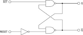
You can easily accomplish that by adding an inverter to one of the inputs. Here, I’ve used NAND gates to create an active-low latch, but I’ve added a NOT gate to invert the RESET input. Thus, the SET-bar input of this inverter is active-low, and the RESET input is active-high.
Sourced by: dummies / Doug Lowe


0 comments:
Post a Comment