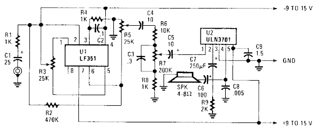
Simple Portable Amplifier Circuit Diagram Ul, an FET op amp needs a bipolar voltage atpins 4 and 7 with a
common ground for optimum gain. You can calculate the gain by dividing
R2 by Rl. Zero-set balance can be had through pins i and 5 through R3.
Put a voltmeter between pin 6 and ground and adjust R3 for zero voltage.
Once you`ve established that, you can measure the ohmic resistance at
each side of R3`s center tap and replace the potentiometer with fixed
resistors. R6, R7, RS,and C3 forrn a tone control that will give you added bass boost, if needed
Simple Portable Amplifier Circuit Diagram


0 comments:
Post a Comment