0-30 Volt Power Supply

linear power supply, shown in the schematic, provides 0-30 volts, at one amp, maximum, using a discrete transistor regulator with op amp feedback to control the output voltage. The supply was constructed in 1975-6 & has a constant current mode that is used to recharge batteries.


With reference to the schematic, lamp, LP2, is a power on indicator. The other lamp (lower) lights when the unit reaches its preset current limit. R5, C2, & Q10 (TO-3 case) operate as a capacitor multiplier. The 36 volt zen-er across C2 limits the maximum supply voltage to the op amps supply pins. D5, C4, C5, R15, & R16 provide a tiny amount of negative supply for the op amps so that the op amps can operate down to zero volts at the output pins (pins 6). A more modern design might eliminate these four parts & use a CMOS rail-to-rail op-amp. Current limit is set by R3, D1, R4, R6, Q12, R10, & R13 providing a bias to U2 that partially turns off transistors Q9 & Q11 when the current limit is reached. R4 is a front panel potentiometer that sets the current limit, R22 is a front panel potentiometer that sets the output voltage (0-30 volts), & R11 is an internal trim-pot for calibration. The meter is a one milliamp meter with an internal resistance of 40 ohms. Switch S1 determines whether the meter reads 0-30 volts, or 0-1 amp. 


A more new circuit might use a single IC regulator, such as the MC78XX, or MC79XX series, immediately after the half wave rectifier, to replace about 30 parts, or at least a high precision zen-er diode to replace D10 as the voltage reference. The LM4040 is such voltage reference & has excellent stability over temperature. IC regulators such as the MC78XX series may finally become obsolete as newer IC regulators are designed, however, discrete transistors, op-amps, & zeners are more generic, have an extended production lifespan, & permit the designer to demonstrate that they understands the principles of linear regulated power supply operation.

Constructing your own Dual Power Supply

Many times the hobbyist desires to have a simple, dual power supply for a project. Existing power supplies may be large either in power output or physical size. a simple Dual Power Supply is necessary.For most non-critical applications the best & simplest choice for a voltage regulator is the 3-terminal type.The three terminals are input, ground & output.

The 78xx & 79xx series can provide up to 1A load current & it have on chip circuitry to prevent damage in the event of over heating or excessive current. That is, the chip basically shuts down than blowing out. These regulators are cheap, simple to make use of, & they make it practical to design a method with plenty of P C Bs in which an unregulated supply is brought in & regulation is done locally on each circuit board.

This Dual Power Supply project provides a dual power supply. With the appropriate choice of transformer & 3-terminal voltage regulator pairs you can basically build a tiny power supply delivering up to amp at +/- 5V, +/- 9V, +/- 12V, +/-15V or +/-18V. You require to provide the middle tapped transformer and the 3-terminal pair of regulators you require:7805 & 7905, 7809 & 7909, 7812 & 7912, 7815 & 7915or 7818 & 7918.

The user must pick the pair they needs for his particular application.

Note that the + & - regulators do not must be matched: you can for example, use a +5v & -9V pair. However,the positive regulator must be a 78xx regulator, & the negative a 79xx. They have built in plenty of safety in to this project so it ought to give plenty of years of continuous service.

Transformer
This Dual Power Supply design makes use of a full wave bridge rectifier coupled with a centre-tapped transformer. A transformer with a power output rated at at least 7VA ought to be used. The 7VA rating means that the maximum current which can be delivered without overheating will be around 390mA for the 9V+9V tap; 290mA for the 12V+12V and 230mA for the 15V+15V. If the transformer is rated by output RMS-current then the worth ought to be divided by one.2 to get the current which can be supplied. For example, in this case a 1A RMS can deliver 1/(one.2) or 830mA.

Rectifier
They use an epoxy-packaged four amp bridge rectifier with at least a peak reverse voltage of 200V. (Note the part numbers of bridge rectifiers are not standardised so the number are different from different manufacturers.) For safety the diode voltage rating ought to be at least to times that of the transformers secondary voltage. The current rating of the diodes ought to be two times the maximum load current that will be drawn.

Filter Capacitor
The purpose of the filter capacitor is to smooth out the ripple in the rectified AC voltage. There's dual amount of ripple is determined by the worth of the filer capacitor: the larger the worth the smaller the ripple.The two,200uF is an appropriate value for all the voltages generated using this project. The other consideration in choosing the correct capacitor is its voltage rating. The working voltage of the capacitor has to be greater than the peak output voltage of the rectifier. For an 18V supply the peak output voltage is one.4 x 18V, or 25V. So they have selected a 35V rated capacitor.

Regulators
The unregulated input voltage must always be higher than the regulators output voltage by at least 3V in order for it to work. If the input/output voltage difference is greater than 3V then the excess potential must be dissipated as heat. Without a heat sink three terminal regulators can dissipate about two watts. A simple calculation of the voltage differential times the current drawn will give the watts to be dissipated. Over two watts a heat sink must be provided. If not then the regulator will automatically turn off if the internal temperature reaches 150oC. For safety it is always best to make use of a small heat sink even in case you do not think you will need.

Stability
C4 & C5 improve the regulators ability to react to sudden changes in load current & to prevent uncontrolled oscillations.

Decoupling
The mono block capacitor C2 & C6 across the output provides high frequency decoupling which keep the impedance low at high frequencies.

LED
Two LED's are provided to show when the output regulated power is online. You do not must make use of the LED's in the event you do not require to. However, the LED on the negative side of the circuit does provide a maximum load to the 79xx regulator which they found necessary in the coursework of testing. The negative 3-pin regulators did not like a zero load situation. They have provided a 470R/0.5W resistors as the current limiting resistors for the LED's.

Diode Protection
These protect chiefly against any back emf which may come back in to the power supply when it supplies power to inductive lots. They also provide additional short circuit protection in the case that the positive output is connected by accident to the negative output. If this happened the usual current limiting shutdown in each regulator may not work as intended. The diodes will short circuit in this case & protect the two regulators.

Dual Power Supply Schematic Diagram

Dual Power Supply Schematic Diagram


Constructing a Universal Power Supply using LM317

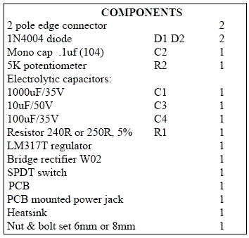
This is a basic,  Universal Power Supply voltage regulator circuit using an LM317, 3-terminal regulator in a TO-220package. The Universal Power Supply output voltage can be set to anywhere in the range one.5V to 30V by selecting resistances. By using a potentiometer, R2, as of the resistors you can dial up the output voltage wanted. Either AC or DC input can be supplied to the PCB by a socket or terminal block. Connection can be either way around. This is because they have provided a bridge rectifier on board. The input DC voltage to the regulator must be at least two.5V above the necessary output voltage. An off/on switch is provided.

For lots of applications (say 12V at 60mA) a heat sink won't be required. The LM317 will provide slightly higher output voltages than 30 volts. However, for most hobbyists over 30V won't be needed. So to make a small PCB they have used some electrolytic capacitors rated to 35 volts. To be safe for continuous operation the maximum input DC voltage to the regulator ought to not be over 33V. With a two.5V to three.0V drop across the regulator this will give a regulated output of 30V. You can draw up to one.5A from the LM317. In case you need higher then use an LM338T rated to 5A.

When outside capacitors are used with any IC regulator it is lovely practice to add protection diodes to prevent the capacitors discharging back in to the regulator in the event of abnormal operating conditions, like a sudden short circuit on the input or the output, or a back emf from an inductive load. That is the function of D one and D Two.

The worth of R1 can range anywhere from 120R to 1200R However, circuits from most other sources settle on using either 220R or 250R. They have used 240R or 250R. The voltage drop across R1is one.25V for all values, and this is the key to the design. one.25V is the reference voltage of the regulator. Whatever current flows through R1 also flows through R2, and the sum of the voltage drops across R1 and R2 is the output voltage. (Additional current Id also flows in R2 but it is usually 50uA so is negligible.)

The design formula are:
VOUT = 1.25 (1 + R2/R1) volts, or alternatively
R2/R1 = (VOUT/1.25) - 1

So in case you know VOUT & R1 is 250R then you can calculate R2. In case you find that the 5K potentiometer used forR2 does not give you the degree of fine control over the voltage output range that you need then you can use these formula to fine-tune R1 & R2 to better suited values.

Universal Power Supply Schematic Diagram

12V DC Switch Mode Power Supply Circuit Diagram

In recent years, the use of switch mode power supply (SMPS) has become more comon as more applications demand for greater power eficiency. It makes use of semiconductor (mostly MOSFET) fast switches to switch DC input that has been rectified at high frequency. The advantages of high frequency switching are that it reduces the size of inductor, capacitors & transformer used. Other advantages of switching power supply over linear power supply are :

1) High Efficiency (up to 90% and above for nice design).
2) Output can be higher than input.
3) Able to operate over a variety of input power supply.
4) Able to have over output.

The setback of using SMPS compared to linear power supply is that it generates electrical noise which contributes to electromagnetic compatibility design issues & more part count.

Buck Converter SMPS
The SMPS circuit below from Power Integration makes use of LNK304 as its high frequency switch. Take note that this circuit is non isolated type which means that the output is not electrically isolated from the input & all testing ought to be completed using an isolation transformer to provide the AC line input to the board.

Make positive that you have electrical safety knowledge & experience before you embark on doing this project.

The features of this project is as summarized below.

Input : 85-265 VAC
Output : 12 V, 120 mA, 1.44 Watt
Low Cost : Only 16 components are needed
No-load power consumption : < 0.2 Watt

12V DC Switch Mode Power Supply (Rise)


Sourced By: Circuitsproject.blogspot.com

Variable DC Power Supply Circuits Diagram

This project provides the schematic & the parts list needed to construct a simple DC Power Supply from an input power supply of 7-20 V AC or 7-30V DC. This project will come in handy in case you use plenty of batteries for your basic electronics project.

Two DC voltage outputs are available; is a fixed regulated 5V for TTL use. The other output is variable from 5V upwards. The maximum output voltage depends on the input voltage. The specified maximum input DC voltage to the regulator is 35V. The maximum input voltage must be two volts higher than the regulated output voltage.

Variable DC Power Supply Circuits Diagram

Variable DC Power Supply Circuits Diagram

The DC Power Supply circuit is based around the 7805 voltage regulator. It's only three connections input, output & ground & it provides a fixed output. The last digits of the part number specify the output voltage, e g. 05, 06, 08, ten, 12,15, 18, or 24. The 7800 series provides up to one amp load current & has on-chip circuitry to close down the regulator if any attempt is made to operate it outside its safe operating area.It can be seen that there's in fact separate circuits in this power supply. 7805 is directly connected as a fixed 5V regulator. The second 7805 has a resistor divider network on the output. A variable 500 ohm potentiometer is used to vary the output voltage from a maximum of 5V up to the maximum DC voltage depending on the input voltage. It will be about 2V below the input DC voltage.

The capacitor across the output improves transient response. The giant capacitor across the input is a filter capacitor to help smooth out ripple in the rectified AC voltage. The larger the filter capacitor the lower the ripple.

For tiny applications the heat sinks won't be needed. The tab on the regulator will dissipate 2W at 25 o C in air. (This is equivalent, for example, to an input voltage of 9V, an output of 5V & drawing 500 m A.) However, as your projects get bigger they will draw more current from the power supply and the regulators will operate at a higher temperature and a heat sink will be needed. You can basically add voltage & current meters to it and put it in to an appropriate plastic case connected to a transformer.

Trouble Shooting Procedure

An LED has been put in to the output of the fixed 5V regulator to indicate that the circuit is working. Poor soldering is the most likely reason that the circuit does not work. Check that all the soldering is done properly. Check that all parts are in their correct position on the PCB. Other items to check are to make sure that the regulators, electrolytic capacitor & bridge rectifier are inserted in the correct orientation.

Variable 5 to 20V DC Supply

If you are looking for a low drop voltage regulator that can provide a power supply of 1A with an output voltage of between 5V and 20V DC, National Semiconductor LM2941 Low Dropout Adjustable Regulator is that you can pick to make use of. It's a typical dropout voltage of 0.5V which means that the input supply need only must be 0.5V DC over the desired output voltage. Its other features include internal short circuit current limit and reverse battery protection.

As shown in the schematic below, the regulator has five pins which consists of the ON/OFF control, Input Voltage, Output Voltage, Ground & Adjustable pins. ON/OFF is used for the purpose of switching on & off of the regulator. The capacitors C1 & E1 are to be placed as close as feasible to the regulator.

The output of the circuit can be varied by varying the worth of potentiometer VR1 from 5V DC to 20V DC. The input voltage is limited from five.5V DC to 30V DC. Resistor R1 must be greater than 1K. The worth of the VR1 that needs to be set is calculated from the formula given below:

VR1 = R1[(Vout/1.275) - 1] ohm

If R1=1K, Vout = 5V, VR1 should be set to 2.9K ohm.

If R1=1K, Vout = 20V, VR1 should be set to 14.7K ohm


5 to 15V Regulated Power Supply

Regulated Power Supply
This project is a normal DC regulated power supply that is a variable DC voltage range from 5V to 15V. It can supply current up to  400mA to power the various circuits for your electronic projects. The voltage output is varied by using the potentiometer V.R1. In this circuit, the input line power supply is designed for 240V.A.C. If 110VAC input is used, alter the ratings of the varistor to 150VAC & the transformer ratio to 110V/12V. 

5 to 15V Regulated Power Supply
Fuse F1 is used as a protection in case there's any short circuit in the circuit. Varistor V1 is connected in parallel to the input of the line voltage to clamp the surge voltage from the line to a reasonable level that helps to protect the transformer & other circuitry. One time the voltage level surge to a high level beyond the ability of the varistor to absorb it, fuse F1 or varistor V1 or both will burn. If this circuit failed after a period of operation, check that the fuse & the varistor are still in nice condition or else replace them.


Diodes D1, D2, D3 and D4 are used to rectify the 12V.A.C voltage to DC voltage. Electrolytic capacitor E1 is used as a smoothing capacitor to reduce the ripple of the DC voltage. The DC voltage is fed in to the input of 7805 regulator where the output DC voltage is obtained. Changing the worth of VR1 will alter the output of the DC voltage. Capacitor C1 is used to filter out high frequency part from the power supply.


2V to 25V Power Supply Schematic

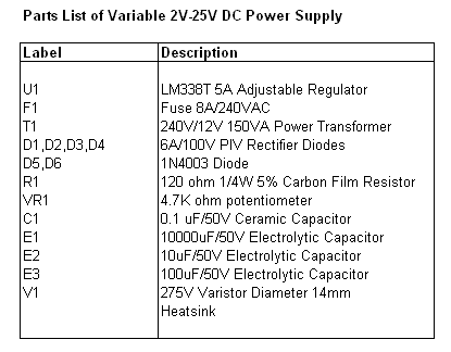
2V to 25 Power supply. This project makes use of a LM338 adjustable three terminal regulator to supply a current of up to 5A over a variable output voltage of 2V to 25V DC. It will come in handy to power up lots of electronic circuits when you are assembling or building any electronic devices. The schematic and parts list are designed for a power supply input of 240VAC. Change the ratings of the parts if 110VAC power supply input is necessary.

2V to 25V Power Supply Schematic

2V to 25V Power Supply Schematic

As shown in the figure above, the mains input is applied to the circuit through fuse F1. The fuse will blow if a current greater than 8A is applied to the method. Varistor V1 is used to clamp down any surge of voltage from the mains to protect the parts from breakdown. Transformer T1 is used to step down the incoming voltage to 24V AC where it is rectified by the diodes D1, D2, D3 & D4. Electrolytic capacitor E1 is used to smoothen the ripple of the rectified DC voltage.

Diodes D5 & D6 are used as a protection devices to prevent capacitors E2 & E3 from discharging through low current points in to the regulator. Capacitor C1 is used to bypass high frequency part from the circuit. Make definite that a large heat sink is mounted to LM338 to transfer the heat generated to the atmosphere.


Simple 12V 5A power supply Regulator Circuit Diagram

This is a Simple 12V 5A power supply Regulator Circuit Diagram.The basic car electrical system gives you around 12-13V when the engine is off and 13-14V when it is running. Not good for a computer, so the basic idea is to use a simple voltage which takes an unregulated voltage in and outputs a regulated voltage. 

 Simple 12V 5A power supply Regulator Circuit Diagram


Simple 12V 5A power supply Regulator Circuit Diagram


The LM1084IT-12 is a 12V, 5A, Low dropout voltage regulator in a TO220 package to which a heatsink will be added. The low dropout feature is nice as the cars supply varies so much. regulator

Simple 13.8V and 20A DC Power Supply Circuit Diagram

This is the Simple 13.8V and 20A DC Power Supply Circuit Diagram. The circuit was designed to create a DC power supply that will be rated with 13.8 V and 20 A while having a current limiter and short circuit protection. 

Simple 13.8V and 20A DC Power Supply Circuit Diagram 


Simple 13.8V and 20A DC Power Supply Circuit Diagram

Using Ic LM338 Make Short Circuit Protection

This is the 1.3 - 32 V / 5A Power Supply w/ Short Circuit Protection . This is a very easy to build power supply that is based on LM338 5A adjustable voltage regulator. I am using the supply for a long time, have no problem yet. Only current adjust is missing but I overcome this situation by using an LCD panel ampermeter.


Using Ic LM338 Make Short Circuit Protection

There is no PCB for the circuit. I took a 3x16 copper plate and strip the unused areas by a knife. If you want you can use analog meters instead of LCD panels.

 Notes

  • Use thick wires for connections.
  • When connecting the LM338 to the heatsink use thermal paste.
  • Use external supplies for LCD panels. They can be 9V batteries. The panels I use draws 1mA current and the batteries last sufficiently long time. If you have small transformers which can supply regulated 9V, you can use them. You need separate transformers for each panel!
  • The transformer should be 100 Watt but if you don't need high current you can try transformers that you already have. (I can draw 6A from 100Watt transformer.)
  • If you have multi winding transformer you can use the diode connections shown in schematic. Diodes must be 10-15 A.
  • Be careful while connecting LM338. Don't put it inverse.
  • Output of your transformer mustn't exceed 25V AC.


This circuit operates with high power! Be careful while building and using it!

Simple 12V 30A Regulated Power Supply Circuit Diagram

This is the Simple 12V 30A Regulated Power Supply Circuit Diagram. This is the Very high current regulated power supply. This circuit require a transformer which have output 24v / 35A. It should be an expensive circuit

Notes:
The input transformer is likely to be the most expensive part of the entire project. As an alternative, a couple of 12 Volt car batteries could be used. The input voltage to the regulator must be at least several volts higher than the output voltage (12V) so that the regulator can maintain its output. If a transformer is used, then the rectifier diodes must be capable of passing a very high peak forward current, typically 100amps or more. The 7812 IC will only pass 1 amp or less of the output current, the remainder being supplied by the outboard pass transistors.


Simple 12V 30A Regulated Power Supply Circuit Diagram


Simple 12V 30A Regulated Power Supply Circuit Diagram


 As the circuit is designed to handle loads of up to 30 amps, then six TIP2955 are wired in parallel to meet this demand. The dissipation in each power transistor is one sixth of the total load, but adequate heat sinking is still required. Maximum load current will generate maximum dissipation, so a very large heat sink is required. In considering a heat sink, it may be a good idea to look for either a fan or water cooled heat sink. In the event that the power transistors should fail, then the regulator would have to supply full load current and would fail with catastrophic results. A 1 amp fuse in the regulators output prevents a safeguard. The 400mohm load is for test purposes only and should not be included in the final circuit. A simulated performance is shown below:


Voltage Probe Circuit Diagram

Detects 1.8 to 230 Volts DC or AC. Minimum parts counting This circuit is not a novelty, but it proved so useful, simple and cheap that it is worth building. When the positive (Red) probe is connected to a DC positive voltage and the Black probe to the negative, the Red LED will illuminate.

Voltage Probe Circuit Diagram


Reversing polarities the Green LED will illuminate. Connecting the probes to an AC source both LEDs will go on. The bulb limits the LEDs current to 40mA @ 220V AC and its filament starts illuminating from about 30V, shining more brightly as voltage increases.

Therefore, due to the bulb filament behavior, any voltage in the 1.8 to 230V range can be detected without changing component values. sourced By : Redcircuits

Note:

A two colors LED (Red and Green) can be used in place of D1 & D2.

Parts:

D1________5 or 3mm. Red LED
D2________5 or 3mm. Green or Yellow LED

LP1_______220V  6W  Filament Lamp Bulb

P1________Red Probe
P2________Black Probe

DC Variable Regulator Power Supply LM1458 and 2N3055

This is the low cost DC Variable Regulator Power Supply LM1458 and 2N3055 circuit Diagram. Power ascendancy is adjustable 3-25 volts and is accepted bound to 2 amps as shown,but may be up to 3 amps in a baby accepted faculty resistor by options (0.3 ohm). 2N3055 transistors 2N3053 and should be in the sinks. actual hot appropriate now and resistor should be rated at 3 watts or more. voltage that is controlled by 1 / 2 of the op amp LM1458 or 1458-AMP. It may be commissioned in the ambit below, but sources advance pressure.

 DC Variable Regulator Power Supply LM1458 and 2N3055


DC Variable Regulator Power Supply LM1458 and 2N3055


Dispensing pin 8 is bound to 30 VDC, which can access by 6.2 volt zener or 5.1 resistor K alternation is 8 pin. best voltage DC accumulation for 1458 and 1558 are 36 and 44, respectively. ability agent should be. As can be accepted in the accepted voltage. Enter at atomic 4 volts college than the adapted achievement voltage but not beat the best bulk of op-AMP beneath low amount conditions.

Agent is apparent as a centermost broke 25.2 volt AC / AMP 2 units to advice ascendancy the 24 volts at 0.7 amps, 15 volts at 2 amps or 6 volts at 3 amps. Achievement AMP 3 is the centermost of the water. agent that changes the 18 volt position. All apparatus charge accept a Radio berth barring of LM1458 op-AMP.

Simple 1A power supply with adjustable output of 0-15 volts

This is the Simple 1A power supply with adjustable output of 0-15 volts circuit diagram. The construction of this power supply circuit is very simple in such a way that the components used are easy to be located while the cost is very cheap. With the biggest provided current at 1 A, the output voltage is adjusted for minimal ripple effect and stabilized in the range of 0 V to 15 V DC. This is made possible by the standard transformer output of 1.5 A with a primary winding voltage of 220 V and secondary voltage of 18 V. The current is being limited by the Zener diode D1 with a rating of 18 V and 1.5 W. The linear potentiometer R2 is responsible for the regulation of current.

 1A power supply with adjustable output of 0-15 volts Circuit Diagram


The power transistor Q1 is a classic type that would require to be placed in a suitable heatsink to suppress the high heat dissipation during the operation of the circuit. The heat dissipation will be continuous during the presence of the highest current. The bridge diode GR1 will provide full wave rectification from the AC input which will also convert the incoming alternating current (AC) input into direct current (DC) output. One good feature of the bridge diode is maintaining the same polarity of the output regardless of the polarity of the input.


The 15V/1 A power supply may be used to handle home automation control system which can be powered by 12 Vdc. They can be made into power adapter models to support a wide variety of applications such as TFT monitors, broadcasting, laptops, digital cameras, telecommunications, PSP’s, routers, notebooks, guitar effects pedals, KVM extenders, iPod’s, scanners, CCTV’s, printers, cassette players, radios, and other portable applications.

Over voltage Protection for Logic Circuit Diagram

Zener diode ZD1 senses the supply, and should the supply rise above 6 V, Ql will turn on. In turn, Q2 conducts clamping the rail. Subsequent events depend on the source supply. It will either shut down, go into current limit or blow its supply fuse. None of these will damage the TTL chips. The rating of Q2 depends on the source supply, and whether it will be required to operate continuously in the event of failure. Its current rating has to be in excess of the source supply. 


 Over voltage protection for logic Circuit Diagram


Using IC LM317 - 40 v 2A Power Supply Circuit Diagram

This is the electronical 40 v 2A Power Supply Circuit Diagram using IC LM317.The primary part of this Power Supply circuit is the voltage regulator IC LM 317. This circuit is ideal for power circuits as the circuit of the power amplifier can deliver a current of 2A. In this circuit the transistor acts as a pass transistor Q1 to increase current capacity. The output voltage is set to 40V by using resistors R5 and R8.


40 v 2A Power Supply Circuit Diagram


Using IC LM317 - 40 v 2A Power Supply Circuit Diagram


Parts List
Resistors: R1 (39 ohm 1 or 2W Resistor)
R2 (22 ohm 1/4W Resistor)
R3 (68K 1/4W Resistor)
R4 (220R 1/4W Resistor)
R5 (47K 1/2W Resistor).

Capacitors: C1 (3300µF 50V Electrolytic Capacitor)
C2, C5 (100nF 63V Polyester Capacitors)
C3 (10µF 63V Electrolytic Capacitor)
C4 (220µF 50V Electrolytic Capacitor).

Active Components: D1 (Diode bridge 4A)
D2 (1N4002 Diode)
D3 (LED any color), U1 (LM317)
Q1 (TIP42A Transistor)
T1 (230V Primary, 40V 2A, Secondary, mains transformer).

Simple Adjustable Power Supply 0-15V / 5A Circuit Diagram

This is the simple Simple Adjustable Power Supply 0-15V / 5A Circuit Diagram. This adapted ability accumulation can be adapted amid a few volts and 15V with P1 and with P2 acclimatize the high absolute ( 15.0V ). R6 amount is 0.7V / Imax area Imax is the best current. At Imax = 5A, R6 is 0.14Ω
 
 Simple Adjustable Power Supply 0-15V / 5A Circuit Diagram


T1 and T2 charge accept heatsinks because ability losses are abundant at a low achievement voltage and a Imax according accepted but you can affix the lamp L to abate this losses.

I’ve body this adjustable ability accumulation and works great! I achievement you’ll adore it too and accept fun body this abundant counterbalanced ability supply.[Link]

Inverting Power Supply Circuit Diagram

This the simple electronic Inverting Power Supply Circuit Diagram. This circuit will provide a negative dc voltage that is approximately equal to the positive input voltage at no load and about 3 V less at 10 mA load. -`~ is from +5 to +15 Vdc. Do not exceed 15 V or Ul might be damaged. 

Simple Inverting Power Supply Circuit Diagram


Simple Inverting Power Supply Circuit Diagram


Sourced by: Streampowers

Simple 12V Power Supply Circuit Diagram

This is the Simple 12V Power Supply  Circuit Diagram.  Simply by connecting the inter-connection as schematically attached with cables or son are properly shielded equipment. A beginner can assemble a schema is 12V in half an hour.12V power supply circuit uses a transformer input 0-15V 3A AC. 

 Simple 12V Power Supply  Circuit Diagram


Simple 12V Power Supply  Circuit Diagram


Unregulated DC supply voltage through a diode bridge integrated component and of the electrolyte capacitor. For a regulated DC voltage needs a 12V zener diode and a 2N3055 transistor with 3A maximum load current capabilities. Thus, the power supply circuit supplying 12V ​​fixed output voltage. 

To connect properly, you must know the pin out of the 2N3055, 2N3055 click to guide technical datasheet. For optimal heat 2N3055 transistor needs a heat sink attached to it. If you want an adjustable output voltage, it requires only small changes in input transistor 2N3055 base with a variable voltage. To this end, may use a LM723 IC.

 Caution in experimentation to a 12V supply circuit.

All updates in Your Inbox

Enter your email address:

Delivered by FeedBurner


Copyright @ 2013 Electronic Circuit Diagrams & Schematics.

Designed by AS & AS