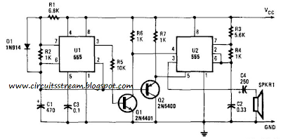
This is a Simple Whooper Circuit Diagram. Integrated circuit Ul is connected as a low-frequency asymmetrical oscillator. Its output is inverted by Ql and fed to the reset terminal of U2 at pin 5. Integrated circuit U2 is configured as an audio oscillator and is enabled when the output of Ul is low. With the voltage at pin 5 of U2 constant, the circuit just` `bleeps.`` The voltage across capacitor CI is fed to the base of Q2, which turns it on and grounds pin 5 of U2.
When the frequency of the reset signal on pin 4 falls, the output frequency of U2 rises. The output then becomes a whoop, starting low in frequency and ending high. Resistor Rl sets the repetition rate and R2 determines the time duration of the whoop. Resistors R3 and R4 set the center-operating frequency.
Whooper Circuit Diagram


0 comments:
Post a Comment