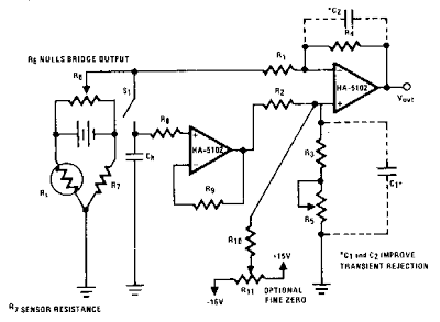
Electronic scales have come into wide use and the HA-510X, as a
very low noise device, can improve such designs. This circuit uses a
staingauge sensing element as part of a resistive Wienbridge. An
auto-zero circuit is also incorporated into this design by including a
sample-and-hold network. The bridge signal drives the inverting input of
a differentially configured HA-5102. The noninverting input is driven
by the other half of the HA-5102 used as a buffer for the holding
capacitor, CH.
Auto Zeroing Scale Circuit Diagram
This second amplifier and its capacitor CH form the sampling
circuit used for automatic output zeroing. The 20-KO resistor between
the holding capacitor CHand the input terminal, reduces the drain from
the bias currents. A second resistor RG is used in the feedback loop to
balance the effect of R8. If R7 is approximately equal to the resistance
of the strain gauge, the input signal from the bridge can be roughly
nulled with R6. With very close matching of the ratio R4/Rl i:o R3/R2,
the output offset can be nulled by closing Sl. This will charge CH and
provide a 0-V difference to the inputs of the second amplifier, which
results in a 0-V output. In this manner, the output of the strain gauge
can be indirectly zeroed. RIO and potentiometer Rll provide an
additional mechanism for fine tuning VouT. but they can also increase
offset voltage away from the zero point. Cl and C2 reduce the circuit`s
susceptibility to noise and transients.


0 comments:
Post a Comment