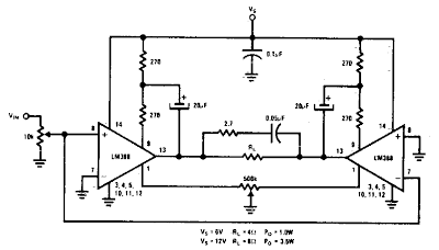
This Bridge Amplifier circuit is for low voltage applications requiring high power
outputs. Output power levels of LO W into 4 ohm from 6 V and 3 V into 8
ohm from 12 V are typical. Coupling capacitors are not necessary since
the output dc levels will-be within a few tenths of a volt of each other. Where critical matching is required the 500 K potentiometer is added and adjusted for zero dc current flow through the load.
Simple Bridge Amplifier Circuit Diagram


0 comments:
Post a Comment