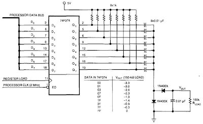
This Simple Up-Controlled Negative Voltage Converter Circuit Diagram was used to produce a variable negative voltage for contrast control of an LCD display. A 74F374 generates a square wave that is ac coupled to a
rectifier and load. By using the uP clock and data from the processor
bus, and properly timed load signal, the dc level generated can be
controlled by the uP.
Simple Up-Controlled Negative Voltage Converter Circuit Diagram


0 comments:
Post a Comment