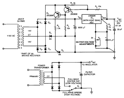
In this circuit, a full-wave bridge is switched to a full-wave center tap to reduce regulator dissipation. SCR D6 switches between configurations. When D6 is off, the circuit is an FWCT rectifier using Dl, D2, and D5. It applies 17 V plus ripple to the regulator input.
The drop across the regulator supplies base drive to Q2. If Q2 is on, Ql is off, and D6 is off. If the regulator voltage drops below about 3 V, Q2 turns off, and turns Ql on, which turns on D6. This changes the circuit to an FW bridge using Dl through D4.
Switching Improves Regulator Efficiency Circuit Diagram


0 comments:
Post a Comment