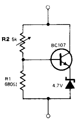
The circuit behaves like a zener diode over a large range of voltages. The current passing through the voltage divider R1-R2 is substantially larger than the transistor base current and is in the region of 8 mA. The stabilizing voltage is adjustable over the range 5-45 V by changing the value of R2. The total current drawn by the circuit is variable over the range 15 mA to 50 mA.This value is determined by the maximum dissipation of the zener diode. In the case of a 250 mW device, this is of the order of 50 mA.
Variable Zener Diode Circuit Diagram


0 comments:
Post a Comment