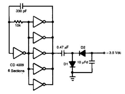
In this Auxiliary Negative Dc Supply Circuit Diagram, IC1 (CD4009) is used as a square-wave oscillator at approximately 25 kHz. CI and Rl set this frequency. C2, Dl, D2, and C3 form a p-p rectifier, which outputs about -3.5 Vdc. This circuit should be useful where a small negative dc supply is required, but only positive dc voltages are available.
Auxiliary Negative Dc Supply Circuit Diagram


0 comments:
Post a Comment