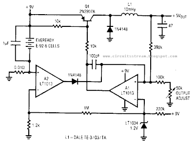
This is the Simple Low Power Switching Regulator Circuit Diagram. A simple battery-powered switching regulator provides 5 V out from a 9-V source with 80% efficiency and 50 mA output capability. When Q1 is on, its collector voltage rises, forcing current through the inductor. The output voltage rises, causing A1`s output to rise.
Q1 cuts off and the output decays through the load. The 100-pF capacitor ensures clean switching. The cycle repeats when the output drops1ow enough for A1 to turn on Ql. The 1-


0 comments:
Post a Comment