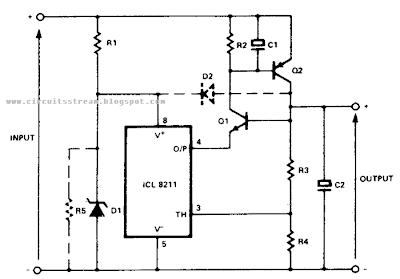
In the Simple Positive Regulator Circuit Diagram, Ql and Q2 are connected in the classic SCR or thyristor configuration. Where higher input voltages or minimum component count are required, the circuit for thyristor boost can be used.
Positive Regulator Circuit Diagram
The thyristor is running in a linear mode with its cathode as the control terminal and its gate as the output terminal. This is known as the remote base configuration.


0 comments:
Post a Comment