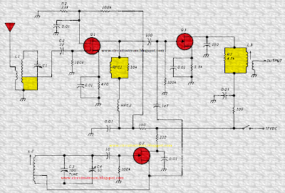
Build a 4-18Mhz Converter Circuit Diagram. The unit consists of RF amplifier Q1, local oscillatorQ2, and mixer Q3. The two bands are covered without a band switch by using an i-f or 3.5 MHz. The oscillator range is 7.5 to 14.5 MHz. Incoming signals from 4 to 11 MHz are mixed with the oscillator to produce the 3.5-MHz i-f.
Signals from 11 to 18 MHz are mixed with the oscillator to also produce an i-f of 3.5 MHz. At any one oscillator frequency, the two incoming signals are 7 MHz apart. Rf amplifier input Cl/L1 comprises a high-Q, lightly loaded, tuned circuit; this is essential for good band separation.
Build a 4-18Mhz Converter Circuit Diagram


0 comments:
Post a Comment