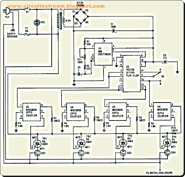
Flasher bulbs use a bi-metallic strip which interrupts the series circuit when the lamp becomes hot.. This is a Best Holiday Lighting Sequencer Circuit Diagram. This is Integrated circuit Ul (a 555 oscillator/timer) is wired as a conventional pulse generator. The frequency of the pulse generator is controlled by potentiometer Rll. Resistor R2 puts a reasonable limit on the highest speed attainable. The output of the pulse generator is fed to the common clock input of U2, a 74C175 quad D-type flip-flop.
Best Holiday Lighting Sequencer Circuit Diagram
Each flip-flop is configured so that its Q output is coupled to the D input of the subsequent flip-flop. Information on the D input of each flip-flop is transferred to the Q (and Q) outputs on the leading edge of each clock pulse. Switch S2 allows you to invert the information on the D input of the first flip-flop at any time during the cycle. This allows you to create a number of different sequences, which are determined by the state of the CQ output at the time of the switching.
However, if S2 is switched to position while all outputs are high or all are low (which seldom occurs), the sequence stops and the outputs remain either all on or all off. If that happens, you only need to switch back to position A for at least one pulse duration, then back to position again. Likewise, S2 should be in position A (pin 4 connected to pin 14) each time the power is turned on. This is because the data on pin 4 must be a logic 1 in order to start a sequence; otherwise all outputs remain at logic 0, regardless of the clock pulses. Each output of the sequencing circuit is connected to an MOC3010 opto isolator/coupler (U3 through U6), which contains an infrared-emitting diode with an infrared-sensitive diac (triac driver or trigger) in close proximity. The diac triggers the triac, which carries the 117-volts ac.
Each time that the infrared- emitting diode receives a logic 1, it turns on and causes the diac to conduct. With the opto isolator/coupler`s internal diac conducting, the triac turns on, and power is supplied to whatever load is plugged into the corresponding ac socket. So, the sequencing circuit and the 117-V ac outputs are optically coupled and are effectively isolated from each other. Power for the sequencing circuit is provided by a 6.3-V miniature transformer. The output of the transformer is rectified by a four-diode bridge circuit, the output of which is filtered by CI (1000- electrolytic capacitor). Capacitor C3 is added at the supply pin of IJ2 to suppress transients.


0 comments:
Post a Comment