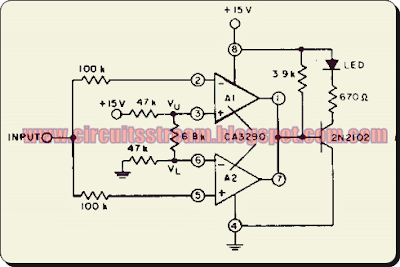
This is a simple High input comparator Circuit Diagram. The inputs of an ideal comparator exhibit infinitely high input resistance, and thus no current flows into its inputs. The circuit uses both halves of the CA3290 BiMOS dual voltage comparator. The LED will be turned `ON` whenever the input signal is above the lower limit (VL) but below the upper limit (Vy).
High input comparator Circuit Diagram


0 comments:
Post a Comment