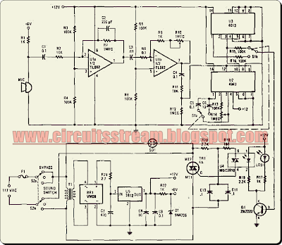
This is a simple voice activated or switch on circuit diagram. With this sound activated switch, control by sound may be very useful, not just on a robot but also for a bit of home automation.This circuit provides either latched switching or timed switching. U1A and UlB provide audio amplification from the microphone. U2 is a retriggerable monostable multivibrator.
Simple Voice Switch on Circuit Diagram
SI A and SIB select either U3, a flip-flop, or U2. R13 and R14 allow a 6- to 60-second timer delay after the sound ceases, in the timed mode. BR1, U5, and associated components form a power supply. Ql drives opto coupler U4 and triggers triac TRl. -If desired, four silicon diode rectifiers connected as a bridge can be substituted for BR1. Just make certain the diodes are rated at least 50V, 1A.


0 comments:
Post a Comment