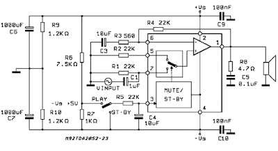
Build a This simple 60 Watt Amplifier Circuit Diagram. TDA2052 is a AB class amplifier which operates with (+,-25V) supply and generates 60 Watt power (sound) output. Since it has very low distortion and it is a AB class amplifier, it can be used in HI-FI systems. TDA2052 has mute and st-by functions so it can be controlled by external digital circuits. Very high temperature and output short circuit protections are included. You should use a heatsink to dissipate the excess heat.
TDA2052 60 Watt Amplifier Circuit Diagram
Parts List
- R1 – Input Impedance
- R2,R3 – Gain (32dB)
- R4 – Input Impedance in Mute Mode
- R5 – Standby Transition Time
- R8 – Output Frequency Balancing
- R9,R10 – Discharge Resistors
- C1 – Input Coupling Capacitor
- C3 – Feedback Coupling Capacitor
- C4 – Standby Transition Time
- C5 – Output Frequency Balancing
- C6,C7 – Supply Stabilizing Capacitors
- C9,C10 – Supply Filter Capacitors


0 comments:
Post a Comment