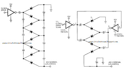
This is a Simple Voltage Multiplier Circuit Diagram. This Simple Voltage Multiplier Circuit Diagram we build to day. how to build lets start. Figure 99-l(a)`s circuit exhibits a high-output impedance as a result of the small effective capacitance of the series-connected capacitors, and it exhibits considerable voltage loss due to all of the diode drops. Further, this circuit requires 2 diodes and 2 capacitors to produce a dc output voltage approximately times the rail voltage. Figure 99-1 (b)`s circuit multiplies more effectively using fewer diodes and capacitors.
The parallel arrangement of the capacitors lets you use smaller capacitors than those required in Fig. 99-1(a). Alternatively, when using the same capacitor values of Fig. 99-1 (a), the output impedance will be lower. Whereas the clock source directly drives only one of the two strings of capacitors in Fig. 99-1(a), Fig. 99-l(b)`s clock drives both strings with opposite phases.
This drive scheme doubles the voltage per stage of two diodes. A final diode is necessary to pick off the dc output voltage because both strings of capacitors now carry the - p ac input-voltage waveform. The ICL7667 dual-FET driver accepts a TTL drive swing and provides a low-impedance push-pull drive to the diode string. This low impedance is particularly helpful when using a long string to raise output voltage to more than 100 V, starting from a low rail voltage.


0 comments:
Post a Comment